Friday, 24 July 2015

Snapmirror Concept

The Basics:

      When mirroring asynchronously, SnapMirror replicates Snapshot copy images from a source volume or qtree to a partner destination volume or qtree, thus replicating source object data to destination objects at regular intervals. SnapMirror source volumes and qtrees are writable data objects whose data is to be replicated. The source volumes and qtrees are the objects that are normally visible, accessible, and writable by the storage system’s clients.

The SnapMirror destination volumes and qtrees are read-only objects, usually on a separate storage system, to which the source volumes and qtrees are replicated. Customers might want to use these read-only objects for auditing purposes before the objects are converted to writable objects. In addition, the read-only objects can be used for data verification. The more obvious use for the destination volumes and qtrees is to use them as true replicas for recovery from a disaster. In this case, a disaster takes down the source volumes or qtrees and the administrator uses SnapMirror commands to make the replicated data at the destination accessible and writable.

SnapMirror uses information in control files to maintain relationships and schedules. One of these control files, the snapmirror.conf file, located on the destination system, allows scheduling to be maintained. This file, along with information entered by using the snapmirror.access option or the snapmirror.allow file is used to establish a relationship between a specified source volume, or qtree for replication, and the destination volume, or qtree where the mirror is kept.

Snapshot Copy Behavior in SnapMirror:

SnapMirror uses a Snapshot copy as a marker for a point in time for the replication process. A copy is kept on the source volume as the current point in time that both mirrors are in sync. When an update occurs, a new Snapshot copy is created and is compared against the previous Snapshot copy to determine the changes since the last update. SnapMirror marks the copies it needs to keep for a particular destination mirror in such a way that the snap list command displays the keyword snapmirror next to the necessary Snapshot copies.

The snapmirror destinations command can be used to see which replica of a particular copy is marked as required at any time. On the source volume, SnapMirror creates the Snapshot copy for a particular destination and immediately marks it for that destination. At this point, both the previous copy and the new copy are marked for this destination. After a transfer is successfully completed, the mark for
the previous copy is removed and deleted. Snapshot copies left for cascade mirrors from the destination also have the snapmirror tag in the snap list command output.

Use the snapmirror destinations -s command to find out why a particular Snapshot copy is marked. This mark is kept as a reminder for SnapMirror to not delete a copy. This mark does not stop a user from deleting a copy marked for a destination that will no longer be a mirror; use the snapmirror release command to force a source to forget about a particular destination. This is a safe way to have SnapMirror remove its marks and clean up Snapshot copies that are no longer needed. Deleting a Snapshot copy that is marked as needed by SnapMirror is not advisable and must be done with caution in order not to disallow a mirror from updating. While a transfer is in progress, SnapMirror uses the busy lock on a Snapshot copy. This can be seen in the snap list command output. These locks do prevent users from deleting the Snapshot copy. The busy locks are removed when the transfer is complete.

For volume replication, SnapMirror creates a Snapshot copy of the whole source volume that is copied to the destination volume. For qtree replication, SnapMirror creates Snapshot copies of one or more source volumes that contain qtrees identified for replication. This data is copied to a qtree on the destination volume and a Snapshot copy of that destination volume is created.

Snapshot examples:

A volume SnapMirror Snapshot copy name has the following format:

dest_name(sysid)_name.number
Example: fasA(0050409813)_vol1.6 (snapmirror)
dest_name is the host name of the destination storage system.
sysid is the destination system ID number.
name is the name of the destination volume.
number is the number of successful transfers for the Snapshot copy, starting at 1. Data ONTAP increments this number for each transfer.

A qtree SnapMirror Snapshot copy name has the following format:

dest_name(sysid)_name-src|dst.number
Example: fasA(0050409813)_vol1_qtree3-dst.15 (snapmirror)
dest_name is the host name of the destination storage system.
sysid is the destination system ID number.
name is the name of the destination volume or qtree path.
src|dst identifies the Snapshot copy location.
number is an arbitrary start point number for the Snapshot copy. Data ONTAP increments this number for each transfer.
In the output of the snap list command, Snapshot copies needed by SnapMirror are followed by the SnapMirror name in parentheses.
Caution: Deleting Snapshot copies marked snapmirror can cause SnapMirror updates to fail.

Modes of SnapMirror:

SnapMirror can be used in three different modes: SnapMirror Async, SnapMirror Sync, and SnapMirror Semi-Sync.

SnapMirror Async:

SnapMirror Async can operate on both qtrees and volumes. In this mode, SnapMirror performs incremental block-based replication as frequently as once per minute.
The first and most important step in this mode involves the creation of a one-time baseline transfer of the entire dataset. This is required before incremental updates can be performed. This operation proceeds as follows.
1. The source storage system creates a Snapshot copy (a read-only point-in-time image of the file system). This copy is called the baseline copy.
2. All data blocks referenced by this Snapshot copy and any previous copies are transferred in case of volume SnapMirror and written to the destination file system. Qtree SnapMirror only copies the latest Snapshot copy.
3. After the initialization is complete, the source and destination file systems have at least one Snapshot copy in common.

After the initialization is complete, scheduled or manually triggered updates can occur. Each update transfers only the new and changed blocks from the source to the destination file system. This operation proceeds as follows:
1. The source storage system creates a Snapshot copy.
2. The new copy is compared to the baseline copy to determine which blocks have changed.
3. The changed blocks are sent to the destination and written to the file system.
4. After the update is complete, both file systems have the new Snapshot copy, which becomes the baseline copy for the next update.
Because asynchronous replication is periodic, SnapMirror Async is able to consolidate the changed blocks and conserve network bandwidth. There is minimal impact on write throughput and write latency.

SnapMirror Sync:

Certain environments have very strict uptime requirements. All data that is written to one site must be mirrored to a remote site or system synchronously. SnapMirror Sync mode is a mode of replication that sends updates from the source to the destination as they occur, rather than according to a predetermined schedule. This helps enable data written on the source system to be protected on the destination even if the entire source system fails. SnapMirror Semi-Sync mode, which minimizes data loss in a disaster while also minimizing the extent to which replication affects the performance of the source system, is also provided.
No additional license fees need to be paid to use this feature, although a free special license snapmirror_sync must be installed; the only requirements are appropriate hardware, the correct version of Data ONTAP, and a SnapMirror license for each storage system. Unlike SnapMirror Async mode, which can replicate volumes or qtrees, SnapMirror Sync and Semi-Sync modes work only with volumes. SnapMirror Sync can have a significant performance impact and is not necessary or appropriate for all applications.
The first step in synchronous replication is a one-time baseline transfer of the entire dataset. After the baseline transfer is completed, SnapMirror will make the transition into synchronous mode with the help of NVLOG and CP forwarding. Once SnapMirror has made the transition into synchronous mode, the output of a SnapMirror status query shows that the relationship is “In-Sync.”

SnapMirror Semi-Sync:

SnapMirror provides a semi-synchronous mode, also called SnapMirror Semi-Sync. This mode differs from the synchronous mode in two key ways:
1. User writes don’t need to wait for the secondary or destination storage to acknowledge the write before continuing with the transaction. User writes are acknowledged immediately after they are committed to the primary or source system’s memory.
2. NVLOG forwarding is not used in semi-synchronous mode. Therefore SnapMirror Semi-Sync might offer faster application response times. This mode makes a reasonable compromise between performance and RPO for many applications.
Note: Before Data ONTAP 7.3, SnapMirror Semi-Sync was tunable, so that the destination system could be configured to lag behind the source system by a user-defined number of write operations or seconds. This was configurable by specifying a variable called outstanding in the SnapMirror configuration file. Starting in Data ONTAP 7.3, the outstanding parameter functionality is no longer available and there is a new mode called semi-sync. When using semi-sync mode, only the consistency points are synchronized. Therefore this mode is also referred to as CP Sync mode.

Configuration of semi-synchronous mode is very similar to that of synchronous mode; simply replace sync with semi-sync, as in the following example:
fas1:vol1 fas2:vol1 – semi-sync

That's it:)


Saturday, 18 July 2015

NetApp iscsi Lun creation

Step:1

Fisrt create a volume for Lun,
Volume name: sanvol
Size : 25GB.


Step:2

Create a qtree for Lun,


Step:3

Open iscsi initiator on windows and connect to filer.
Click discover portal and give filer IP, port details like following,


Step:4

Successfully connected to filer,


Step:5

Go to configuration tan and copy the initiator name.
While creating the igroup we should provide this IQN number.


Step:6

Go to Filer and check if iscsi is enabled, if not enable the iscsi and start the service,


Step:7

Now create a Lun using "lun create" command,
-s : size of lun
-t : type of operating system


Step:8

Create igroup using "igroup create" command,

igroup create -i -t windows igroupname iqnname
-i : for iscsi need to mention i, for FC need to mention "-f"
-t : Operating system


Step:9

map the Lun to igroup using "lun map" command and give lun id at the end,


Step:10

Check the lun details using lun show -v command,


Step:11

Go to windows client, -> manage -> storage > data ONTAP DSM management.
Here you can see newly created lun and bottom it shows multipath details,


Step:12

Click on Disk management and then initialize, format and give the drive letter like following,


 Click finish to complete the setup,


Now you can see the Disk1 online and healthy,


Here you can see newly created 20GB lun in E:Drive,


That's it :)

NetApp Snapshot Technology


         NetApp Snapshot point-in-time copy software protects data with no performance impact and uses minimal storage space. 

This software, the original and most functional point-in-time copy technology, enables you to protect your data with no performance impact and minimal consumption of storage space.

It enables you to create point-in-time copies of file systems, which you can use to protect data—from a single file to a complete disaster recovery solution.

You can use Snapshot technology while applications are running and create Snapshot copies in less than a second, regardless of volume size or level of activity on your NetApp system.

Make up to 255 Snapshot copies per volume, instantly, to create online backups for user-driven recovery.

Snap create and Restore:

Step:1

The share "share1" already created in fas01 filer,


Step:2

This share has already mapped to windows server. 
around 3.2 gb used out of 20gb.


Step:3

You can see 2 folders there in share1.


Step:4

From Filer take a snapshot,

snap create -V volname snapshotname.


Step:5

From Windows client delete the 2 folders,which are resides in share1.(After taking snapshot),


2 folders are deleted,


Step:6

From filer side, do snap restore,

snap restore -t vol -s snapshotname  volumename


Step:7

Check in windows client side, now that 2 folders are available,


That's it :)

Friday, 24 April 2015

Vserver configuration for NAS

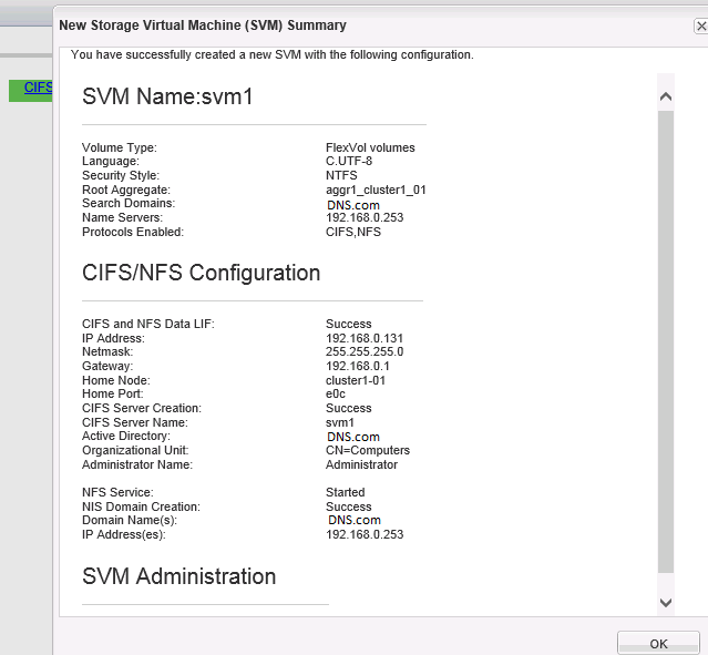
         Here we will create a new SVM named svm1 on cluster and will configure it to serve out a volume over NFS and CIFS. We will be configuring two NAS data LIFs on the SVM, one per node in the cluster.

Step:1

Open System manager => Storage virtual machines =>  Click "create"

Need to provide SVM name, Data protocols, Root aggregate & DNS details,


Step:2

In this step need to specify data interfaces (LIF) and CIFS server details,


Step:3

Specify the password for an SVM specific administrator account for the SVM, which can then be used to delegate admin access for just this SVM.


Step:4

New Storage Virtual Machine Summary window opens displaying the details of the newly created SVM.


Step:5

The SVM svm1 is now listed under cluster1 on the Storage Virtual Machines tab. The NFS and CIFS protocols are showing in right panel,which indictates that those protocols are enabled for the selected SVM svm1.


Creating Vserver through CLI:

Create Vserver using "vserver create" command,


We are not yet any LIFs defined for the SVM svm1. Create the svm1_cifs_nfs_lif1 data LIF for svm1:


Configure the DNS domain and nameservers for the svm1,


That's it :)

Thursday, 23 April 2015

SVM (Vserver) & LIF Concepts

         Storage Virtual Machines (SVMs), previously known as Vservers, are the logical storage servers that operate within a cluster for the purpose of serving data out to storage clients. A single cluster may host hundreds of SVMs, with each SVM managing its own set of volumes (FlexVols), Logical Network Interfaces (LIFs), storage access protocols (e.g. NFS/CIFS/iSCSI/FC/FCoE), and for NAS clients its own namespace.

You explicitly choose and configure which storage protocols you want a given SVM to support at SVM creation time, and you can later add or remove protocols as desired.. A single SVM can host any combination of the supported protocols.

An SVM’s assigned aggregates and LIFs determine which cluster nodes handle processing for that SVM. As we saw earlier, an aggregate is directly tied to the specific node hosting its disks, which means that an SVM runs in part on any nodes whose aggregates are hosting volumes for the SVM. An SVM also has a direct relationship to any nodes that are hosting its LIFs. LIFs are essentially an IP address with a number of associated characteristics such as an assigned home node, an assigned physical home port, a list of physical ports it can fail over to, an assigned SVM, a role, a routing group, and so on. A given LIF can only be assigned to a single SVM, and since LIFs are mapped to physical network ports on cluster nodes this means that an SVM runs in part on all nodes that are hosting its LIFs.

When an SVM is configured with multiple data LIFs any of those LIFs can potentially be used to access volumes hosted by the SVM. Which specific LIF IP address a client will use in a given instance, and by extension which LIF, is a function of name resolution, the mapping of a hostname to an IP address. CIFS Servers have responsibility under NetBIOS for resolving requests for their hostnames received from clients, and in so doing can perform some load balancing by responding to different clients with different LIF addresses, but this distribution is not sophisticated and requires external NetBIOS name servers in order to deal with clients that are not on the local network. NFS Servers do not handle name resolution on their own.

DNS provides basic name resolution load balancing by advertising multiple IP addresses for the same hostname. DNS is supported by both NFS and CIFS clients and works equally well with clients on local area and wide area networks. Since DNS is an external service that resides outside of Data ONTAP this architecture creates the potential for service disruptions if the DNS server is advertising IP addresses for LIFs that are temporarily offline. To compensate for this condition DNS servers can be configured to delegate the name resolution responsibility for the SVM’s hostname records to the SVM itself so that it can directly respond to name resolution requests involving its LIFs. This allows the SVM to consider LIF availability and LIF utilization levels when deciding what LIF address to return in response to a DNS name resolution request.

LIFS that are mapped to physical network ports that reside on the same node as a volume’s containing aggregate offer the most efficient client access path to the volume’s data. However, clients can also access volume data through LIFs bound to physical network ports on other nodes in the cluster; in these cases clustered Data ONTAP uses the high speed cluster network to bridge communication between the node hosting the LIF and the node hosting the volume. NetApp best practice is to create at least one NAS LIF for a given SVM on each cluster node that has an aggregate that is hosting volumes for that SVM. If additional resiliency is desired then you can also create a NAS LIF on nodes not hosting aggregates for the SVM as well.

A NAS LIF (a LIF supporting only NFS and/or CIFS) can automatically failover from one cluster node to another in the event of a component failure; any existing connections to that LIF from NFS and SMB 2.0 and later clients can non-disruptively tolerate the LIF failover event. When a LIF failover happens the NAS LIF migrates to a different physical NIC, potentially to a NIC on a different node in the cluster, and continues servicing network requests from that new node/port. Throughout this operation the NAS LIF maintains its IP address; clients connected to the LIF may notice a brief delay while the failover is in progress but as soon as it completes the clients resume any in-process NAS operations without any loss of data.

The number of nodes in the cluster determines the total number of SVMs that can run in the cluster. Each storage controller node can host a maximum of 125 SVMs, so you can calculate the cluster’s effective SVM limit by multiplying the number of nodes by 125. There is no limit on the number of LIFs that an SVM can host, but there is a limit on the number of LIFs that can run on a given node. That limit is 256 LIFs per node, but if the node is part of an HA pair configured for failover then the limit is half that value, 128 LIFs per node (so that a node can also accommodate it’s HA partner’s LIFs in the event of a failover event).

Each SVM has its own NAS namespace, a logical grouping of the SVM’s CIFS and NFS volumes into a single logical filesystem view. Clients can access the entire namespace by mounting a single share or export at the top of the namespace tree, meaning that SVM administrators can centrally maintain and present a consistent view of the SVM’s data to all clients rather than having to reproduce that view structure on each individual client. As an Administrator maps and unmaps volumes from the namespace those volumes instantly become visible or disappear from clients that have mounted CIFS and NFS volumes higher in the SVM’s namespace. Administrators can also create NFS exports at individual junction points within the namespace and can create CIFS shares at any directory path in the namespace.

Tuesday, 21 April 2015

Troubleshooting CIFS issues


• Use "sysstat –x 1" to determine how many CIFS ops/s and how much CPU is being utilized.

• Check /etc/messages for any abnormal messages, especially for oplock break timeouts.

• Use "perfstat" to gather data and analyze (note information from "ifstat","statit", "cifs stat", and "smb_hist", messages, general cifs info).

• "pktt" may be necessary to determine what is being sent/received over the network.

• "sio" should / could be used to determine how fast data can be written/read from the filer.

• Client troubleshooting may include review of event logs, ping of filer, test using a different filer or Windows server.

• If it is a network issue, check "ifstat –a", "netstat –in" for any I/O errors or collisions.

• If it is a gigabit issue check to see if the flow control is set to FULL on the filer and the switch.

• On the filer if it is one volume having an issue, do "df" to see if the volume is full.

• Do "df –i" to see if the filer is running out of inodes.

• From "statit" output, if it is one volume that is having an issue check for disk fragmentation.

• Try the "netdiag –dv" command to test filer side duplex mismatch. It is important to find out what the benchmark is and if it’s a reasonable one.

• If the problem is poor performance, try a simple file copy using Explorer and compare it with the application's performance. If they both are same, the issue probably is not the application. Rule out client problems and make sure it is tested on multiple clients. If it is an application performance issue, get all the details about:
◦ The version of the application
◦ What specifics of the application are slow, if any
◦ How the application works
◦ Is this equally slow while using another Windows server over the
network?
◦ The recipe for reproducing the problem in a NetApp lab.

• If the slowness only happens at certain times of the day, check if the times coincide with other heavy activity like SnapMirror, SnapShots, dump, etc. on the filer. If normal file reads/writes are slow:
◦ Check duplex mismatch (both client side and filer side)
◦ Check if oplocks are used (assuming they are turned off)
◦ Check if there is an Anti-Virus application running on the client. This can cause performance issues especially when copying multiple small files.
◦ Check "cifs stat" to see if the Max Multiplex value is near the cifs.max_mpx option value. Common situations where this may need to be increased are when the filer is being used by a Windows Terminal Server or any other kind of server that might have many users opening new connections to the filer. What is CIFS Max Multiplex?
◦ Check the value of OpLkBkNoBreakAck in "cifs stat". Non-zero numbers indicate oplock break timeouts, which cause performance problem.

Sunday, 19 April 2015

Adding a node to cluster

    Manually run the cluster setup wizard to add the node to the cluster .This is exactly the same procedure you would follow to add even more nodes to the cluster, the only differences being that you would assign a different the IP address and possibly a different management interface port name.

Step:1

Launch a Putty section and type Cluster setup command,


Step:2

It ask's you want to create a new cluster or join an existing cluster, type "join", and it will show you the existing cluster interface configuration. If you want to use the same existing cluster configuration then type "yes"


Step:3

Here it will ask a cluster name in which you want to add a node. just hit enter,


Step:4

In this step need to configure SFO (Storage failover) if you use HA system. As we dont have HA cannot configure SFO.


Step:5

In this step need to configure the Node, assinging IP,Interface,Gateway..etc.


That's it. Successfully added a node to cluster1.


Wednesday, 15 April 2015

Create a New Aggregate on Cluster Node

                 Disks are the fundamental unit of physical storage in clustered Data ONTAP and are tied to a specific cluster node by virtue of their physical connectivity (i.e. cabling) to a given controller head.
             
Data ONTAP manages disks in groups called aggregates. An aggregate defines the RAID properties for a group of disks that are all physically attached to the same node. A given disk can only be a member of a single aggregate.

By default each node has one aggregate known as the root aggregate, which is a group of the node’s local disks that host the node’s Data ONTAP operating system. A node’s root aggregate is created during Data ONTAP installation in a minimal RAID-DP configuration, meaning it is initially comprised of 3 disks (1 data, 2 parity), and is assigned the name aggr0. Aggregate names must be unique within a cluster so when the cluster setup wizard joins a node it must rename that node’s root aggregate if there is a conflict with the name of any aggregate that already exists in the cluster. If aggr0 is already in use elsewhere in the cluster then it renames the new node’s aggregate according to the convention aggr0_<nodename>_0.

A node can host multiple aggregates depending on the data sizing, performance, and isolation needs of the storage workloads that it will be hosting. When you create a Storage Virtual Machine (SVM) you assign it to use one or more specific aggregates to host the SVM’s volumes. Multiple SVMs can be assigned to use the same aggregate, which offers greater flexibility in managing storage space, whereas dedicating an aggregate to just a single SVM provides greater workload isolation.

Create a Aggr using System Manager:
--------------------------------------------
Step:1

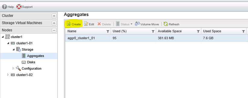
Go to Cluster1 => Node cluster1-01 => Storage => Click "Aggregates",

It shows list of aggregates in that node owns. In aggr menu click "create"


Step:2

Now opens aggregate create wizard, click next,


Step:3

Here need to specify aggregate name and raid type, I'm going to specify aggregate name as "aggr_cluster1_01" and raid type is "RAID DP"


Step:4

Here it's shows aggregate details and select disk option, click "Select disks"


Step:5

Select the disk group from the table and specify the no of disks that you want to add to the aggregate.

I just selected only 2 disks, but for RAID-DP min 3 disks required, so here i'm selecting 8 disks,

Step:6

Review the details and click create,


Step:7

Aggregate "agg1_cluster1_01" successfully created.


Check the newly created aggregate in the aggregates menu,


Create a aggregate in CLI:
-------------------------------

Create a new aggregate using the "aggr create" command, with 6 disks,


Check the newly created aggregate using aggr show command,


That's it :)